Analyzing line audio input with Arduino
Have you made a music or audio sensitive Arduino project but are tired of fiddling with microphone input levels? Perhaps you’re just wondering how to measure the voltage of an audio source, like a stereo output or a headphone output.
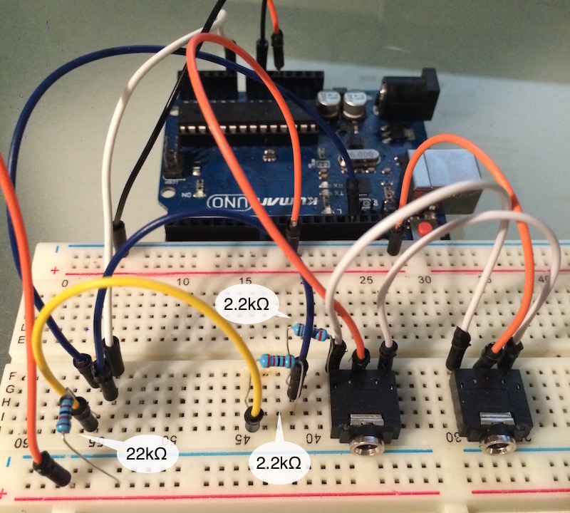
This post covers how to measure line-level audio amplitude peaks with an Arduino project plugged into the audio source. All you’ll need are a few resistors used to construct a voltage divider circuit. A headphone or audio jack helps, but you can also connect exposed audio cable wires directly into your project. For this example I have two headphone jacks wired together, one for input, the other for pass-through output.
Basics
Your typical stereo audio cable has 3 wires in it: the ground, the left signal, and the right signal. The signals have a voltage range of ±1V. That’s not much of a voltage difference, but we can setup the Arduino to analyze that bipolar signal.
Circuit diagram
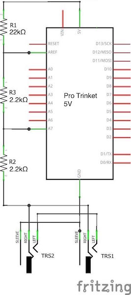
In this example, I am using an Adafruit Pro Trinket 5V, but you can use any Arduino board running at 5V with an AREF pin such as the Arduino Metro, Mega, etc.
Sampling range
Connect the 5V power supply to the AREF analog reference pin through a 22kΩ resistor. This is to get a better resolution of the sampled values of the audio signal. The reason why we get a better resolution is that the 0 to 1024 values of the ADC are no longer mapped to 0-5V but to 0-2.96V (2.96V because of the 22kΩ resistor). To understand why a 22kΩ resistor is used and how I have calculated 2.96V have a look at the analog reference article on the Arduino website.
Sampling offset
There is one problem if you want to analyze an audio signal with an Arduino. The signal is mirrored around 0V. Therefore we get both positive and negative voltage peaks. Since Arduino can’t handle negative voltages we have to get rid of them and create an offset.
As you can see in the schematic above I used a basic voltage divider circuit with two 2.2kΩ resistors to solve this problem. Since they have both the same resistance the signal now alters around 1.48V (2.96V/2) and we got rid of those negative voltages.
Audio connection
When connecting the two audio jacks, you can wire both right and both left channels to each other. Then connect both center ground pins together and wire them to the Arduino GND. You can connect either the left or the right channel to the analog input pin of the Arduino. In this configuration, either jack can function as an input or pass-through output jack.
Example sketch
Verifying that the circuit is working correctly is super simple.
void setup() {
  Serial.begin(9600);
}

void loop() {
  Serial.println(analogRead(A7));
}
That’s it!
Analog values
Use the Serial Plotter in Arduino to view the values produced by analog read. You should see a a rough peak waveform on the graph display. The analog values range between 300 to 720 with my setup, with 510 hovering as the center point.
More examples
To see source code and example projects for audio analyzers using this circuit, check out my Spectra series on github. They cover more advanced stuff like setting the analog-to-digital converter to free-run mode, for real-time continuous audio analysis with an FFT algorithm.